BPSK (Binary Phase Shift Keying) is one of the most basic digital modulation schemes used by many applications from 10BASE-T Ethernet to everyday wireless communication systems. BPSK modulates a carrier by introducing 180 degrees of phase shift at every data transition.
Costas Loop is a carrier synchronisation mechanism required to reliably demodulate PSK (in this case, BPSK) modulated signals.
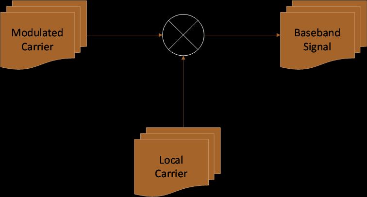
The following is the diagram of a typical BPSK demodulator:

In a BPSK demodulator, the baseband signal (binary data signal) is recovered by mixing the BPSK modulated carrier to the local carrier that is in phase with the carrier that was used to modulate the BPSK modulated carrier.
Any phase difference between the modulated carrier and the local carrier would cause the baseband signal to attenuate by the factor of cos(φ), where φ is the phase angle between the modulated carrier and the local carrier (note that a 90-degree phase angle would cause the baseband signal to completely attenuate and therefore carry no meaningful information). In order to maximise the baseband signal amplitude, it is necessary to synchronise the local carrier to the carrier used to modulate the BPSK modulated carrier, such that the phase angle between the two carriers is 0.
At first glance, one may suggest using a Phase Locked Loop (PLL) for this purpose, but a PLL would lock onto every 180-degree phase shift introduced to the carrier at every data transition and the recovered local carrier would subsequently contain such phase shifts; thereby, making it impossible to recover the baseband signal.
Costas Loop is similar to the Phase Locked Loop in the sense that it locks onto the frequency and phase of its input signal and produce an output signal that is identical in frequency and phase to the input signal, but it is inherently immune to a 180-degree phase shift of the input signal (i.e. BPSK modulated carrier).
The following is the diagram of a Phase Locked Loop:

For BPSK modulated carrier input, the signal at each numbered node in the diagram above can be expressed as follows:
(1) BPSK Modulated Carrier Input: A BPSK modulated carrier is a sinusodial signal with angular frequency ω and phase φ. s(t) is Polar NRZ (Non-Return-to-Zero) encoded data that holds the value of -1 or 1.
![]()
(2) Mixer Output: The mixer output is a product of the BPSK modulated carrier (Eq. 1) and the output of the 90-degree phase shifter (Eq. 5).
![]()
(3) Low-Pass Filter Output: The LPF output is the mixer output without the high frequency term (i.e. 2ω).
![]()
(4) Numerically Controlled Oscillator Output: The NCO output is a sinusoidal signal with angular frequency ω and phase θ.
![]()
(5) 90-degree Phase Shifter: The output of the 90-degree phase shifter is a sine function.
![]()
Note from the equations above that the Polar NRZ encoded data, s(t), affects the feedback function (Eq. 3) of the NCO. This implies that the output of a Phase Locked Loop is dependent on the sign of the input signal (hence, 180-degree phase shift) and is therefore not suitable for the purpose of carrier recovery.
Also note that this is an interpretation of Phase Locked Loop specific to Binary Phase Shfiting; however, a more generalised form of interpretation also applies to Quadrature Phase Shfit Keying (QPSK) and higher order of Phase Shift Keying modulation schemes.
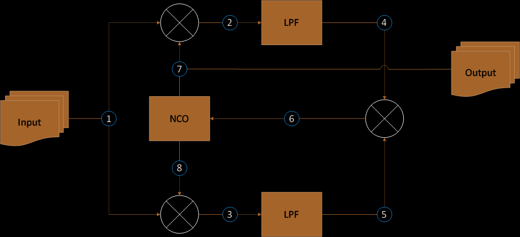
Now that we have made it clear how we cannot use a Phase Locked Loop for carrier recovery, let’s take a look at the Costas Loop. The following is the diagram of a Costas Loop:

For BPSK modulated carrier input, the signal at each numbered node in the diagram above can be expressed as follows:
(1) BPSK Modulated Carrier Input: A BPSK modulated carrier is a sinusodial signal with angular frequency ω and phase φ. s(t) is Polar NRZ encoded data that holds the value of -1 or 1.
![]()
(2) Cosine Mixer Output: The output of the cosine mixer is a product of the BPSK modulated carrier (Eq. 1) and the in-phase output of the NCO (Eq. 7).
![]()
(3) Sine Mixer Output: The output of the sine mixer is a product of the BPSK modulated carrier (Eq. 1) and the quadrature output of the NCO (Eq. 8).
![]()
(4) Cosine Low-Pass Filter Output: The output of the cosine LPF is the cosine mixer output without the high frequency term (i.e. 2ω).
![]()
(5) Sine Low-Pass Filter Output: The output of the sine LPF is the sine mixer output without the high frequency term (i.e. 2ω).
![]()
(6) Feedback Mixer Output: The output of the feedback mixer is a product of the cosine LPF output and the sine LPF output. Note that s(t) is either -1 or 1 and squaring it would effectively eliminate it from the feedback function.
![]()
(7) Numerically Controlled Oscillator In-Phase Output: The in-phase output of the NCO is a sinusoidal signal with angular frequency ω and phase θ.
![]()
(8) Numerically Controlled Oscillator Quadrature Output: The quadrature output of the NCO is a sinusoidal signal with angular frequency ω and phase θ. Note that the quadrature output denotes a 90-degree phase shift from the in-phase output.
![]()
Note from the equations above that the Polar NRZ encoded data, s(t), is completely eliminated from the feedback function (Eq. 6) because it is squared in the process of mixing the two LPF outputs containing s(t). This implies that the Costas Loop is not sensitive to a 180-degree phase shift and can therefore be used to generate a stable local carrier for demodulating a BPSK modulated carrier.
The Costas Loop feedback function and the loop behaviour can be summarised as follows:
| 2(θ – φ) | Feedback | Lock |
| 0 ~ π/2 | Negative | 0 |
| π/2 ~ π | Positive | π |
| π ~ 3π/2 | Negative | π |
| 3π/2 ~ 2π | Positive | 2π |
From the table above, we can observe that the Costas Loop can potentially lock π radians (180 degrees) out of phase if the phase difference between the input signal and the NCO output is between π/2 and 3π/2 radians.
The implication of this is that, if the loop locks 180 degrees out of phase, all demodulated data will be the inverse of what was used to modulate the carrier at the transmitter side. For example, if the Polar NRZ data sequence used to modulate the carrier were [ -1 1 -1 -1 1 -1 ], the demodulated data sequence would be [ 1 -1 1 1 -1 1 ].
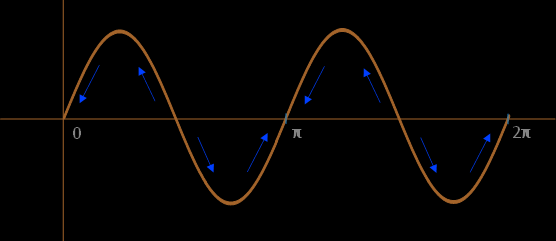
The following is a graphical representation of the BPSK Costas Loop feedback response:

While I labeled the node 7 (NCO in-phase output) as the output of the Costas Loop and it is indeed the recovered carrier output, upon closer inspection, one would realise that the Costas Loop in itself is a demodulator- mixing the local carrier (node 7) with the BPSK modulated carrier input (node 1) and low-pass filtering it. It is, in fact, possible to implement a BPSK demodulator solely out of a Costas Loop by carefully adjusting the LPF parameters.
(c) 2016 Stephanos Ioannidis
A bit off-topic to write it here, but Happy New Year 2017, and my best wishes to you and all your upcoming projects.
Greetings.